Ethernet/IP Integration
- 16 May 2025
- 打印
- PDF
Ethernet/IP Integration
- 更新于 16 May 2025
- 打印
- PDF
The content is currently unavailable in Chinese (Simplified, People's Republic of China). You are viewing the default English version.
文章摘要
您觉得此摘要对您有帮助吗?
感谢您的反馈
The OV80i vision system supports real-time communication with EtherNet/IP-based PLCs. This guide explains how to configure cyclic I/O connections, map data structures, and use Overview’s Node-RED tools to access both global and ROI-level inspection results.
Overview
The OV80i functions as an EtherNet/IP adapter, while your PLC operates as a scanner (or master). Once configured, the devices exchange structured data every cycle using a compact and predictable format.
Supported Features
Cyclic I/O communication - 20–10,000 ms cycle time support
Data throughput - Up to 256 bytes in each direction
Custom data handling - Read/write Node-RED data as part of the active recipe
Network Setup
Assign a static IP address to the OV80i.
Ensure both the OV80i and your PLC are on the same subnet.
Make sure EtherNet/IP traffic is allowed on your network.
Put the OV80i into Ethernet/IP Mode by selecting it on the Industrial Ethernet tab in the sidebar.
.png)
PLC Configuration
Download the OV80i EDS file and import it into your PLC development environment
Add the OV80i as a new EtherNet/IP device using the EDS file.
Set the Input and Output Assembly instances and Requested Packet Interval (RPI).
Map assembly data to appropriate tags in your PLC.
Confirm data is being exchanged in real-time.
Input Assembly (OV80i → PLC)
The input assembly contains data sent from the OV80i to the PLC on every cycle. This includes system status, inspection results, recipe information, and optional ROI breakdowns.
Byte | Bit 7 | Bit 6 | Bit 5 | Bit 4 | Bit 3 | Bit 2 | Bit 1 | Bit 0 |
|---|---|---|---|---|---|---|---|---|
0 | Online / Startup Complete | Recipe Switch Ack | Trigger Ack | Trigger Ready | ||||
1 | Busy | Recipe Switch Error | Trigger Error | |||||
2 | Inspection Pass | Inspection Completed / Result Available | Exposure Complete | |||||
3 | ||||||||
4 | ||||||||
5 | ||||||||
6 - 7 | ||||||||
8 - 9 | Current Recipe ID (16-bit integer) | |||||||
10 - 11 | ||||||||
12 - 13 | Inspection ID (16-bit integer) | |||||||
14 - 15 | ||||||||
16 - 256 | ROI Results Assembly or Custom Data from NodeRED | |||||||
Output Assembly (PLC → OV80i)
The output assembly contains control data sent from the PLC to the OV80i. You can use it to trigger inspections, change recipes, or pass in custom parameters.
Byte | Bit 7 | Bit 6 | Bit 5 | Bit 4 | Bit 3 | Bit 2 | Bit 1 | Bit 0 |
|---|---|---|---|---|---|---|---|---|
0 | Recipe Switch Request | Trigger | ||||||
1 | ||||||||
2 | ||||||||
3 | ||||||||
4 - 5 | Recipe ID (16-bit integer) | |||||||
6 - 256 | Custom Data For NodeRED | |||||||
Timing and Handshake Behavior
.png)
Custom Data Support
The OV80i can accept or return additional custom data as part of your Node-RED flow.
PLC → OV80i
Write external flags, thresholds, or counters to influence logic in Node-RED
OV80i → PLC
Return calculated values, measurements, timestamps, or conditional outputs
Custom data fits into the extended portion of the assemblies, starting after the core signals and recipe info.
ROI Result Breakdown (Classification Recipes Only)
For classification recipes, you can expose per-ROI results to the PLC using Overview’s custom Node-RED node: Format data for PLC.
How it works:
Placed between All Blocks Output Data and Send Data to PLC in the Node-RED flow
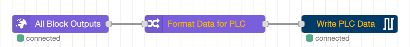
Automatically populates a structured ROI region starting at byte 16 in the input assembly
Supports up to 4 ROIs per inspection
Each ROI includes:
ROI ID
Pass/fail bit
Confidence score
Reserved bytes for future use
⚠️ Format Data for PLC Node works with Classification Recipes Only
Byte | Bit 7 | Bit 6 | Bit 5 | Bit 4 | Bit 3 | Bit 2 | Bit 1 | Bit 0 |
|---|---|---|---|---|---|---|---|---|
16 | Aligner Success | |||||||
17 - 18 | Aligner Confidence (unsigned 16-bit integer) | |||||||
19 - 20 | Aligner Angle (signed 16-bit integer) | |||||||
21 - 23 | Aligner: Reserved for Future Data | |||||||
24 | ROI 0 ID (8-bit integer) | |||||||
25 | ROI 0 Pass | |||||||
26 - 27 | ROI 0 Confidence (unsigned 16-bit integer) | |||||||
28 - 31 | ROI 0: Reserved for Future Data | |||||||
32 | ROI 1 ID (8-bit integer) | |||||||
33 | ROI 1 Pass | |||||||
34 - 35 | ROI 1 Confidence (unsigned 16-bit integer) | |||||||
36 - 39 | ROI 1: Reserved for Future Data | |||||||
40 | ROI 2 ID (8-bit integer) | |||||||
41 | ROI 2 Pass | |||||||
42 - 43 | ROI 2 Confidence (unsigned 16-bit integer) | |||||||
44 - 47 | ROI 2: Reserved for Future Data | |||||||
48 | ROI 3 ID (8-bit integer) | |||||||
49 | ROI 3 Pass | |||||||
50 - 51 | ROI 3 Confidence (unsigned 16-bit integer) | |||||||
52 - 55 | ROI 3: Reserved for Future Data | |||||||
本文对您有帮助吗?