Trigger using a PLC
- 30 Dec 2024
- Print
- PDF
Trigger using a PLC
- Updated on 30 Dec 2024
- Print
- PDF
Article summary
Did you find this summary helpful?
Thank you for your feedback!
Connect the camera to the PLC of your choice by following Ethernet/IP - Establishing Communication.
Program the logic using a similar example
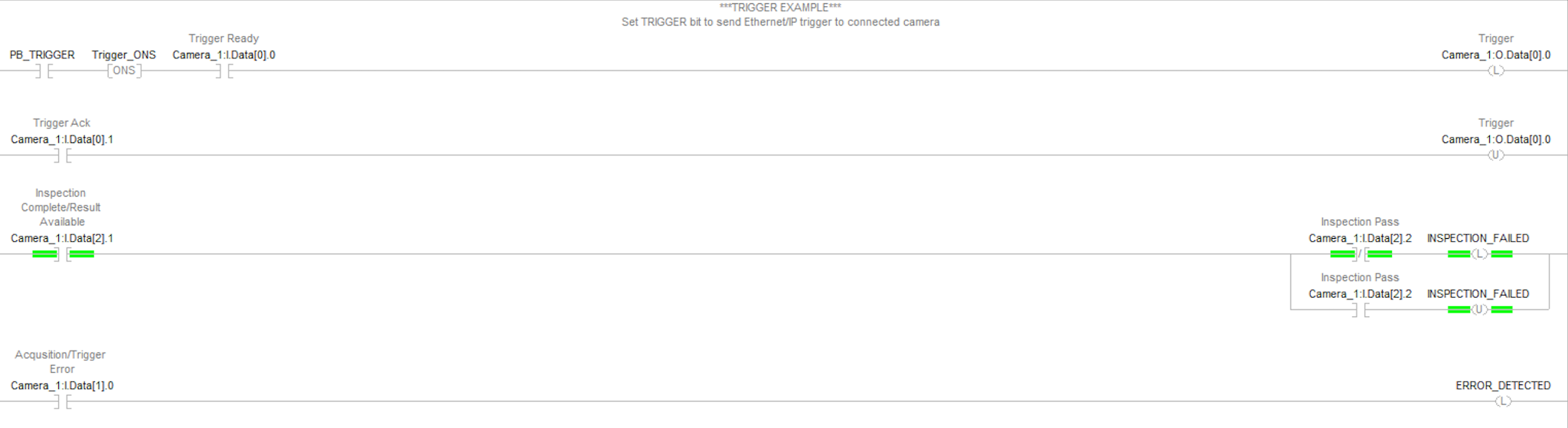
.png "image(106).png")
Camera Triggering and Status Monitoring
This section explains the process of triggering the camera and monitoring its status using PLC logic. Each signal and its corresponding action are detailed to ensure proper integration and functionality.
PB_TRIGGER
Function: Acts as a control signal from the PLC logic to determine when to trigger the camera.
Description: This tag is essential for initiating the camera trigger process. When activated, it serves as an input that starts the sequence of events leading to image capture.
Trigger_ONS
Function: Provides a one-shot signal to ensure the trigger occurs only during the rising edge.
Description: The Trigger_ONS generates a single pulse when the PB_TRIGGER signal transitions from low to high. This prevents multiple triggers from occurring due to signal fluctuations or noise.
Camera_1:I.Data[0].0
Function: Indicates that the camera is ready to be triggered.
Description: This bit, coming from the PLC, must be monitored to confirm that the camera is ready to accept a trigger signal. The camera will not respond to trigger signals unless this bit is high.
Camera_1:O.Data[0].0
Function: Sends the trigger signal to the camera.
Description: This output bit from the PLC must be set high to initiate image capture. It must be latched, meaning it remains high until the camera acknowledges receipt of the trigger. The acknowledgment is received via the Camera_1:I.Data[0].1 signal, which then allows the trigger bit to be unlatched.
Camera_1:I.Data[0].1
Function: Acknowledges the trigger from the camera.
Description: Once the camera has received the trigger signal, this bit will turn high. The PLC logic must monitor this bit to unlatch the Camera_1:O.Data[0].0 trigger signal, completing the trigger sequence.
Result Availability and Status
Camera_1:I.Data[2].1 :
Function: Indicates that the result of the image processing is available.
Description: This bit turns high when the camera has processed the image and the result is ready to be read.
- Camera_1:I.Data[2.2] :
Function: Provides the pass/fail status of the image.
- Description :
If this bit is high, it indicates a pass.
If this bit is low, it indicates a failure.
Error Handling
Camera_1:I.Data[1].0 :
Function: Indicates an error condition.
Description: This bit turns high if there is an error with the camera. The error bit will latch and remain high until the error is cleared. Proper error-handling logic should be implemented in the PLC to reset this bit and handle the error condition accordingly.
Summary of Key Signals:
PB_TRIGGER: Initiates the camera trigger process.
Trigger_ONS: Ensures a single trigger pulse.
Camera_1:I.Data[0].0: Camera readiness indicator.
Camera_1:O.Data[0].0: Trigger signal, must be latched until acknowledgment.
Camera_1:I.Data[0].1: Acknowledgment of trigger from the camera.
Camera_1:I.Data[2].1: Indicates result availability.
Camera_1:I.Data[2].2: Pass/fail status indicator.
Camera_1:I.Data[1].0: Error indicator, latched until cleared.
By following these steps and monitoring the specified signals, the integration of the camera with the PLC logic can be effectively managed, ensuring reliable image capture and processing.
Was this article helpful?