IO Block and Node-RED Logic
- 05 May 2025
- Imprimir
- DF
IO Block and Node-RED Logic
- Actualizado el 05 May 2025
- Imprimir
- DF
The content is currently unavailable in Spanish (Mexico). You are viewing the default English version.
Resumen del artículo
¿Te ha resultado útil este resumen?
Gracias por tus comentarios
This document provides reference information about the custom nodes developed by Overview for use with the OV20i camera system. These specialized nodes extend Node-RED's capabilities to make vision inspection workflows simpler to implement and manage.
Introduction to Node-RED
Node-RED is a flow-based programming tool that provides a browser-based editor for connecting hardware devices, APIs, and online services. It represents a low-code approach to automation, making it accessible to users regardless of programming background. The OV20i camera system leverages Node-RED as its automation platform, allowing you to create powerful inspection workflows with minimal coding.
Information
More information about the Node-RED platform can be found on their website - https://nodered.org/
Overview Custom Nodes
The OV20i camera comes pre-installed with specialized nodes developed by Overview to simplify vision inspection tasks. These custom nodes handle common vision-specific operations and integrate seamlessly with the camera's hardware and software capabilities.
Why Custom Nodes?
Our custom nodes are designed to:
- Simplify complex vision processing tasks
- Provide standardized interfaces for common inspection operations
- Ensure compatibility with industrial automation systems
- Reduce implementation time for typical machine vision applications
All Block Outputs Node
1. Purpose and Functionality
2. Key Features
3. Configuration Options
Classification Block Logic Node
1. Purpose and Functionality
The Classification Block Logic node evaluates results from the classification system and determines whether conditions are met based on configurable rules. This node is essential for transforming visual inspection results into actionable decisions.
2. Key Features
- Outputs a boolean value (true/false) based on classification results
- By default, outputs true if all inspections return "pass" class
- Customizable rules for complex decision logic
- Ability to evaluate multiple class outputs simultaneously
3. Configuration Options
Format Data for PLC

1. Purpose and Functionality
The PLC Format Node converts inspection data into formats compatible with industrial PLCs (Programmable Logic Controllers). This ensures seamless integration between the vision system and factory automation equipment.
2. Key Features
- Formats data according to PLC requirements
- Supports both little-endian (Allen-Bradley PLCs) and big-endian formats
- Configurable data mapping for different controller types
3. Configuration Options
Inspection Pass/Fail
1. Purpose and Functionality
The Final Pass/Fail Output Node establishes and stores the definitive inspection result. This node serves as the authoritative source for whether an item has passed or failed inspection, making this information available to other systems.
2. Key Features
- Creates a clear binary pass/fail outcome
- Provides persistent storage of inspection results
- Can trigger downstream actions based on result
3. Configuration Options
Save to Library
1. Purpose and Functionality
The Save to Library node allows users to save inspection images to the OV20i's internal library for future reference and analysis. This enables the creation of an inspection history database directly on the camera.
2. Key Features
- Automatic image storage with associated metadata
- Configurable storage criteria (pass/fail conditions, sampling rate)
- Maintains a searchable database of inspection results
- Includes timestamps and inspection parameters with saved images
3. Configuration Options
Capture Metadata
1. Purpose and Functionality
The Capture Metadata node attaches contextual information to inspection results, providing valuable reference data that helps identify and categorize each capture.
2. Key Features
- Structured metadata storage as key-value pairs
- Support for both string and numeric values
- Customizable metadata fields
- Preserved across inspection sessions
3. Configuration Options
Output Nodes
1. Purpose and Functionality
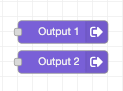
Output nodes control the digital outputs on the M12 connector of the OV20i, turning pins on or off based on boolean values to communicate with external systems.
2. Key Features
- Direct control of hardware output pins
- Simple boolean operation (true = ON, false = OFF)
- Integration with industrial equipment
- Consistent performance with minimal configuration
3. Configuration Options
| Parameter | Description | Default |
|---|---|---|
| Output Pin | Which physical pin to control | DO0 - DO1 |
| Initial State | Starting state of the output | OFF |
| Pin # | Pigtail | Default |
|---|---|---|
| 10 | Violet | Output 1 |
| 11 | Gray / Pinkt | Output 2 |
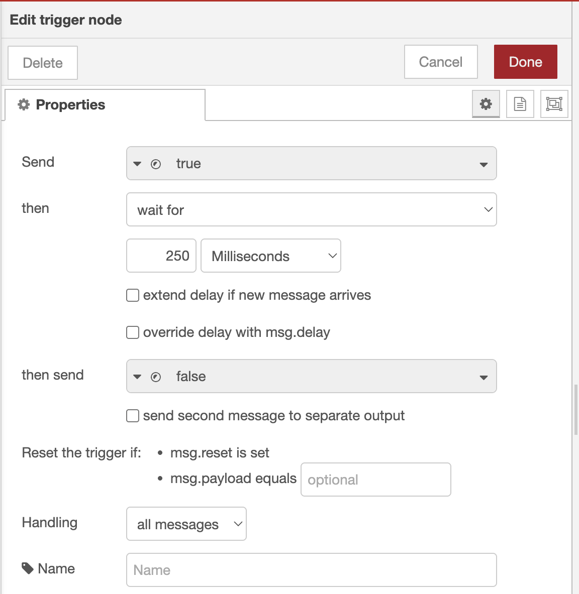
Important
There is no pulse configuration from the DO as itself, so you need to add a trigger to create a pulse.
Input Nodes
1. Purpose and Functionality
Input nodes read the status of digital inputs on the OV20i's M12 connector, allowing external signals to trigger actions within the Node-RED flow.
2. Key Features
3. Configuration Options
Onboard Status LED
1. Purpose and Functionality
The Onboard Status LED node controls the status LED located on top of the OV20i, providing a visual indicator of system states and inspection results.
2. Key Features
- Simple interface for controlling the LED
- Multiple color options for different status indications
- Support for blinking patterns
- Visual feedback without external hardware
3. Configuration Options
¿Fue útil este artículo?